Cast Aluminum Tooling
The reason cast tooling has a longer lead time than CNC machined or fabricated tooling is down to the fact that it is a multi-step process which uses a variety of materials.
3D design for Cast Aluminum Tooling
The process begins with a 3D model which can be provided in either .Step or .IGES format. The 3D model is adjusted to account for shrinkage based on a linear equation. This linear equation is known as the shrink factor. The shrink factor takes into account the shrinkage of the molten aluminum, and the plastic resin being used.
Model making
In some cases the model can be shaped by hand from Poplar wood, however this requires a skilled craftsman with years of experience. Usually the 3D Design is used to create a model on a multi axis CNC router. Models are often made from ‘RenShape tooling board’ or polyurethane foam. It critical that the surface finish of the model is smooth and non-porous, so a sealant is a used to ensure this.
Pattern making
The next step in the cast aluminum tooling process requires a material with high strength to create a female pattern from the model. There are two materials that have been used in the pattern making industry. Tooling plaster and fiberglass; both are very hard and dense, which allows fine details to transfer from the model to the pattern. A frame is built around the model which creates the parting line for the final mold. This is a very time consuming and important phase as the position of a parting line defines the way the final rotomolded product is demolded. Once the pattern making material has set, the model is removed from the pattern using traditional woodworking tools such as a coping saw. The pattern is now ready to be used for the casting process.
Cast Aluminum Tooling the mold
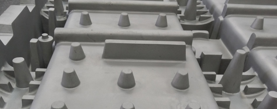
Aluminum ingots are melted down at 122°F in a furnace for pouring. A sand cavity is formed from the cope and drag sands being set together. The cope and drag sands are formed from the fiberglass pattern. Then, the molten aluminum is poured into the cavity via a series of runners and gates. Once the castings have been poured, they must sit and cure for a predetermined time frame. The runners and sand are broken away from the casting leaving the raw castings which are later sanded and finished. The finished casting that is formed replicates the detail created from the female pattern.
Parting line match, fasteners, framing and surface finish
Now that the raw castings have been formed, a clamping or fastener system must be added to each section of the tool to hold the parting line together. But before this, a critical process is required where the parting lines of each mating point of the tool are matched to ensure there is correct alignment between the mold cavities. Steel framing is placed onto the base mold so that it can be secured to the rotational molding oven in such a way that allows the mold to be serviced optimally. The inside of the cavity is then textured with the relevant medium to match the customer’s surface finish specifications.